|
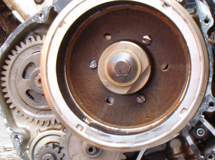
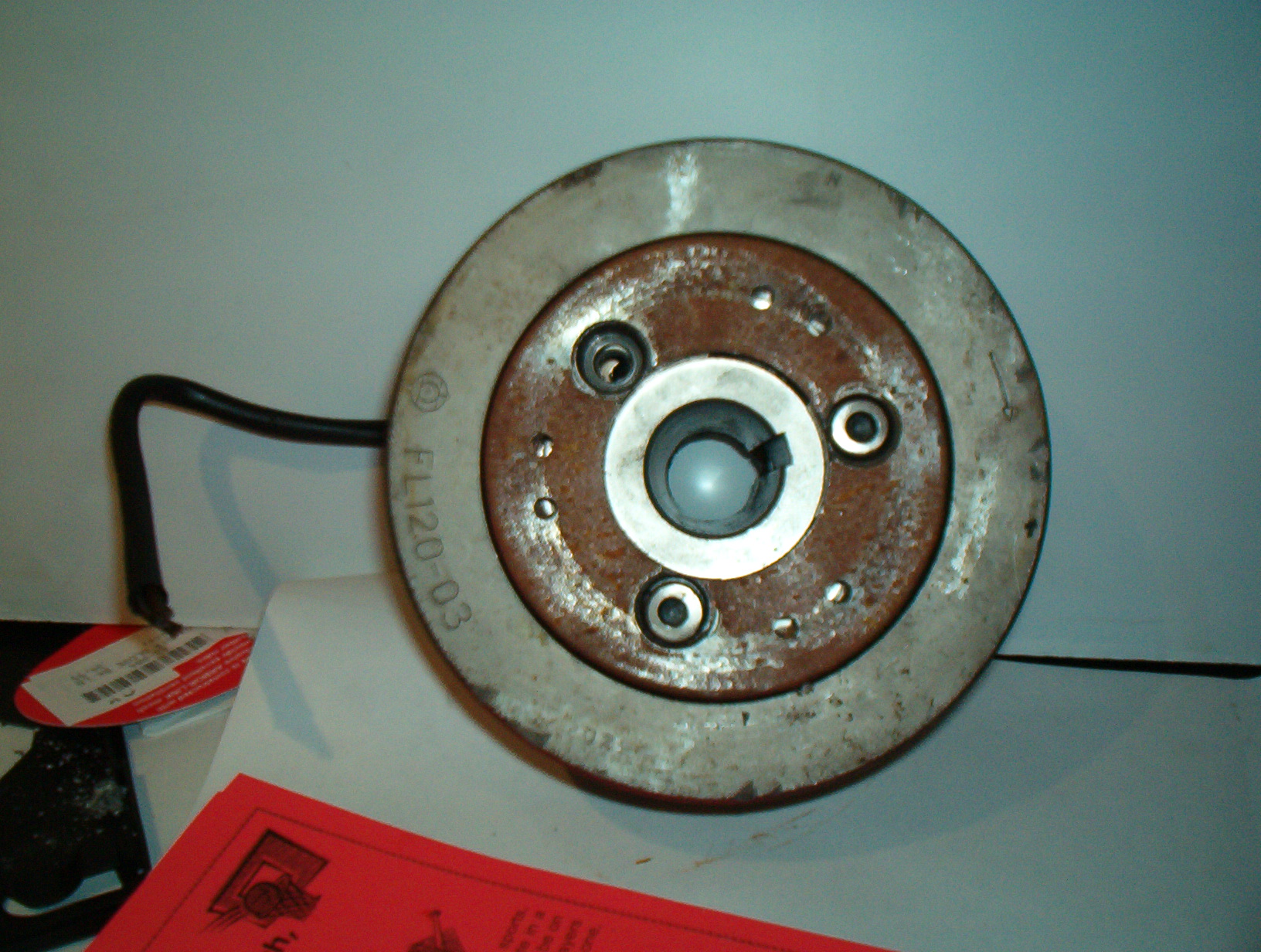
This is the view of the flywheel you will see
when you remove the left cover. Note the 3
starter clutch bolts & the 3 threaded
puller holes. These bolts have had the
modification done.
|
|
|
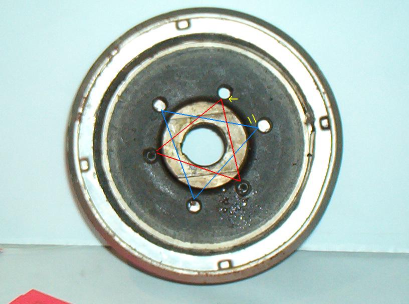
The Starter clutch is on the backside of the
flywheel. If you look closely at this pic you
will see that there are 6 threaded holes, and
that 2 of the 3 bolts are installed.
The red lines denote the clutch bolt holes,
The Blue lines denote the puller holes,
The yellow marks show that the puller holes
On this rotor the puller holes are further
from the center than the clutch holes.
On this rotor the two sets of holes are
different distances from the center, and the
clutch holes will only line up with one set.
On other rotors all 6 holes will fit the clutch.
|
|
|
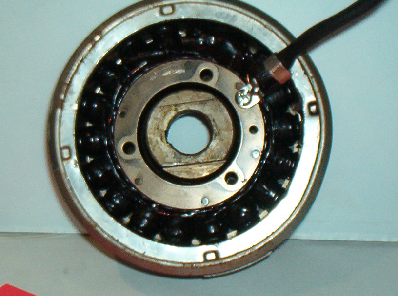
This is just a view of how the stator (which is normally mounted
in the cover) fits inside the rotor
|
|
|
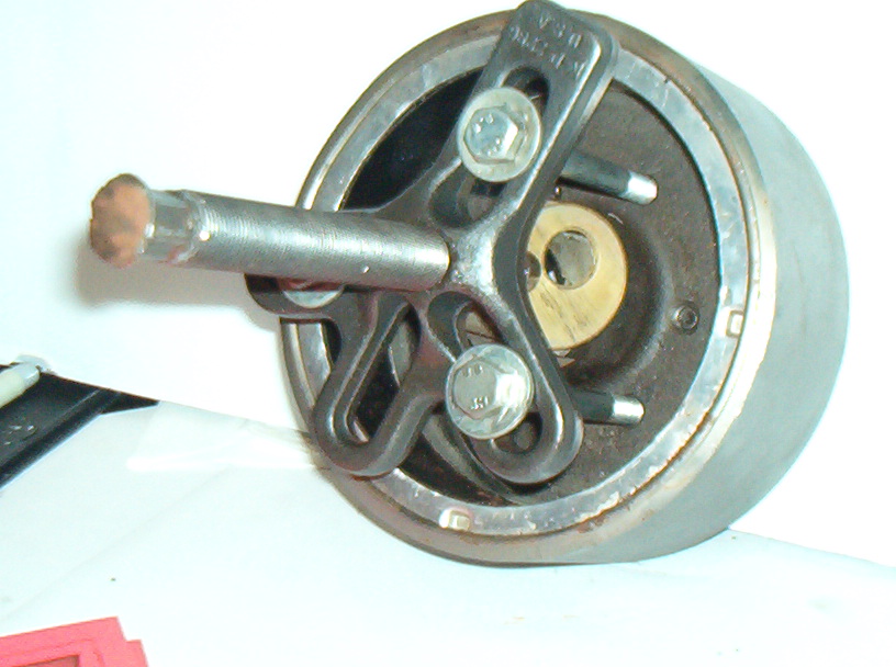
Here is the puller mounted in the rotor. Note the mushroomed
end of the center screw from hitting it with a BIG hammer, there
are flats on the side of the screw to tighten it with a wrench.
Do not thread the 3 puller bolts in more than about 5/16 of an
inch or you will damage the clutch.
The copper piece in the center is just there
to hold the puller tight for the pic.
|
|
|
This is the end of the puller center screw that goes up
against the crankshaft. the wide piece at the end is a 'foot'
or 'swivel' that needed to be removed. It was actually resting
on the rotor rather than the crankshaft. you may need to remove
yours too. |

|
|
This is the backside of the rotor with the starter clutch (partially)
attached. This is what you will see once the rotor is off (minus
the wires) Not shown in this pic is the starter gear that fits
inside the center of the clutch. the rollers in the clutch ride
on the gear hub. if you pull the gear off with the rotor, springs,
rollers & caps will not go flying...
|
|
